Improving the odds with 10:1 Input DC DC Converters
23rd February 2022Improving the odds with 10:1 Input DC DC Converters
Nearly all electronic products require some form of power conversion product to convert the primary energy supply, be it ac mains, or a dc source such as a battery, to a voltage suitable for the equipment within. Today’s design engineers have a huge array of products available to choose from, which can be a blessing AND a curse. This article provides advice on when a 10:1 (or greater) input range converter is the optimal choice and when other choices more accurately suit the specification’s needs.
The choices for ac input products are relatively straightforward if we ignore thermal and physical characteristics. Equipment destined for Europe, and most of Asia will operate at 230Vac, whilst North America and Japan requires equipment to operate at 100 – 110Vac. Not too long ago, power supplies consisted of an iron-cored transformer followed by a linear regulator. In order to maximise efficiency, the downstream converters could only cope with a maximum input voltage ratio of 2:1.
Modern switching power supplies however can now easily cope with a 4:1 input range which means that a single unit can operate at 80% of the 110Vac range (88V) and 120% of the 230V limit (264V). We are also seeing a trend extending this range up to 305Vac to meet modern lighting specifications. The choice for our engineer though is huge.
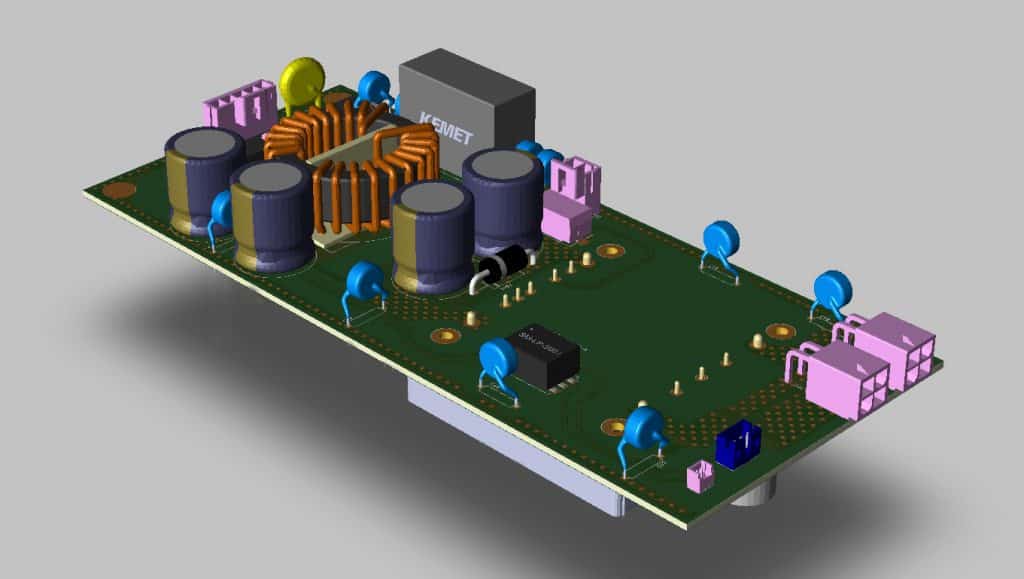
Fig 1 – Typical custom assembly of a 10:1 input DC DC Converter
As far as DC DC converters are concerned there are similar trends emerging. DC inputs tend to focus around standard battery voltages, which in the industrial sector are 12V, 24V, 48V, 72V, and 110Vdc (the last 2 are common in power generation and the railway industry). Whilst 4:1 input products have been around for some time that cover either 12V & 24V, or 24V & 48V, we are now seeing products on the market that can, in theory, cope with all of these supply voltages in a single range.
This might sound attractive, but there are pitfalls that engineers should be aware of when using 10:1 or greater, input range dc dc converters. This guide looks at some of the elements that should be considered. As the basis for this study, we will use a 100W converter with an input range of 16.8V to 154V. This is common in the railway industry and would cover 24V input systems down to 70% of the nominal (16.8V) and 110V input systems incorporating a 140% surge (154Vdc).
Input Current
Let’s take a look at the difference in input current we will see across the 2 extremes
If we assume an efficiency of 90% for our converter, then the max input current at 110V will be:
100 / (110 * 0.90) = 1.01A
But at 24V this will be:
100/(24*0.90) = 4.6A
and at the very bottom of the range
100/(16.8*0.90) = 6.6A
The design engineer must consider track thickness and copper weights at this extreme.
Within the converter itself, this huge swing in current will have a big impact on the efficiency of the device. The heart of any converter with be the switching transistors. These need to be dimensioned to accommodate both the peak voltages seen in the system and also the peak currents. Losses in a MOSFET transistor are dominated by the resistance of the transistor when it is in its “On” state, known as RDSon. RDSon tends to be lower for devices with lower working voltages but with an ultra-wide input product, we need to dimension the device for the highest possible input.
The losses in the transistor in this state are calculated as I2 * RDSon. Given the figures above the losses in the main switching transistors could be 40 times higher than at the lowest input range.
This also needs to be considered when we consider the filter components, especially common mode and differential inductors. Typically, we need chokes with higher inductance at lower voltages, but we need to dimension for worst-case at both minimum and maximum voltages, which could end up with chokes much larger than they need to be.
Fusing, Inrush Current & Reverse Polarity Protection
Once again we need to dimension our input fuse/breaker to be able to cope with the high nominal currents at low input voltages, but we also need a high dc voltage rating which limits our choices. We might also want to consider our input fuse in conjunction with a reverse-biased diode or transorb as part of a reverse polarity protection system. Given the high nominal currents at low input voltages, there is a possibility that the fuse simply won’t blow if the input is connected incorrectly.
If active polarity protection is preferred, this might be as simple as a series diode, but we have the same problem we’ve faced before in that we need a high voltage rating as well as a high current rating. These devices could be large, expensive, and inefficient.
Capacitors
The input circuits of dc dc circuits are full of capacitors which serve 3 main purposes, a) a local, low impedance energy source for our switching transistors, b) electrical noise suppression, and c) providing power hold up in the event of supply interruption.
Looking again at our 100Watt converter we will need to dimension our input capacitors to work continuously at 154V, so 200V ratings should be considered a minimum. Let’s look at dimensioning some capacitance for hold-up. Assume we want the system to keep running for 20mS if the input supply disappears. We need enough energy in the input capacitors to power the dc dc from a nominal 24V down to its minimum input of 16.8V (It will switch off at this point).
So input energy is:
100Watts/0.90(efficiency)* 20mS = 2.2 Joules
Total energy in the capacitor will be 0.5 x C*V2 with V equal to 24V, but the converter is going to turn off at 16.8Vdc. The usable energy in the capacitor is therefore 0.5 x C*(242 – 16.82).
So C will have to be:
> 2.2/0.5(242 – 16.82) = 15000uF
This wouldn’t be too bad if we rated the capacitors for a 24V system at say 50V, but at 200V they will take up considerable real estate.
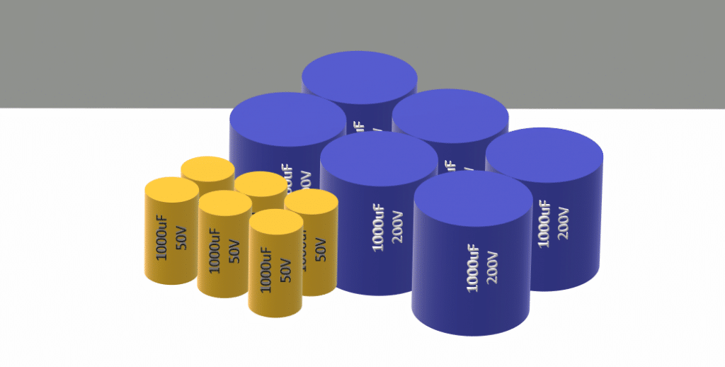
Fig 2 – Capacitor real estate for equivalent hold up at different voltages
Many wide input converters do actually incorporate a boost stage that has a higher voltage intermediate bus which helps to mitigate this problem, but users should be aware that many don’t.
Power dissipation / Losses
As discussed earlier, it’s not easy designing a system that is all things to all people. Most ultra-wide input converters suffer from their lowest efficiency at lower input voltages due to the inefficiency of the switching transistors. A typical unit might have an efficiency of 90% at 110V in but this can drop to 85% at 24V or even as low as 82% at 16.8V, which is the bottom end of the continuous range for 24V. Even at 85% efficiency, we have to allow for 33% more heat to be dissipated in the system which means larger heatsinks and more real estate.
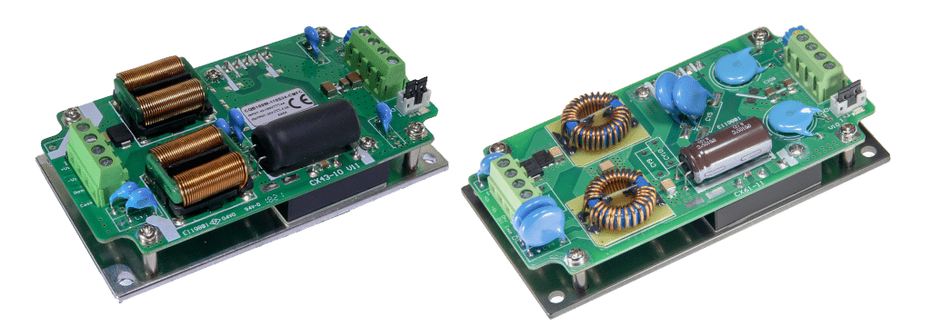
Fig 3 – On the left a 100 Watt 40 – 160V input converter and on the right a 50 Watt 16.8 – 160V converter
Conclusions
A single solution that is suitable for use in every situation is extremely attractive, but there are always compromises; in terms of the cost, size, and performance of the device.
To summarise, engineers and project managers need to consider wider implications such as:
- How much larger is single unit solution going to be compared to discreet solutions for different input voltages?
- Will the lower efficiency impact the reliability of my system though higher component temperatures?
- Does the simplified BOM really lead to lower costs given the higher costs of the converter?
| Input range | Power | Worst-case efficiency | Size | Volume price |
| 16.8 to 154V | 20W | 85% | 2” x 1” | £30.00 |
| 9 to 36V or 40 to 160V | 20W | 89% | 2” x 1” | £22.00 |
| 9 to 36V or 40 to 160V | 40W | 88% | 2” x 1.2” | £30.00 |
Table 1 shows that for a given size of converter, we have 3 options available
- 20 Watts of power, covering all inputs, but the unit is approximately 20% more expensive and has 25% more heat dissipation
- For the same power we can reduce costs by going for bespoke input ranges
- We can provide more power in the same space envelope.
Here at Relec, we have over 40 years’ experience in the power sector and have a wide range of products available. We pride ourselves on being able to offer the best solution for any given application. There will be occasions when a “one-size-fits-all” solution works perfectly, and we can help engineer these solutions for you. Just as importantly, we can take you through the pros and cons of a variety of alternative options and endeavor to offer a solution that offers better reliability at a lower cost.

GET IN TOUCH TODAY – 01929 555700
Here at Relec Electronics, we have worked closely with our key suppliers for over 40 years. We specialise in many industries, including; automotive, industrial, transportation, instrumentation & defence. We have a team of dedicated engineers ready to support you throughout the design process. We also carry stock of all standard modules and accessories for next day delivery.
Let’s make this easy and call us today.
Follow us on Facebook, LinkedIn & Twitter for updates on all of the latest Power Conversion products.
Sign up to our monthly newsletter below, and never miss out on our updates of industry news, we release news/blog pages weekly with news from the power and display industries.
Relec Electronics holds the highest standards towards finding you the ideal solution for your application. We truly believe “Standard is Just the Beginning”. Get in touch with our technical team today.
sign up for our newsletter
Enter your email address below
LET’S MAKE THIS EASY. CALL 01929 555 700
why choose relec?
-
Faster
Our aim is to get back to you with an initial response within the hour.
-
Attention to detail
We pride ourselves on getting you the right product, at the right price and on time.
-
New ideas
We are constantly looking for latest technology and products for your applications.
-
Beyond standard
It’s not just about the product. Our service goes way beyond the norm.
-
Easy
We want to make your life as simple as it can be. Call us to find out what we can offer.


